2. Up to a certain period, development of loco-motive design brought with it mainly an increase in weight of individual locomotives, the increase in power being proportionate to the increase in weight. This increase in power made possible notable economies in railroading. Of late years, however, the demand for still further economies has led locomotive designers to strive to increase the efficiency of the locomotive, and thus give increased power per unit of locomotive weight. Among the means adopted successfully to this end, are the use of superheated steam, various fuel and labor-saving devices, improved boiler design, more efficient steam distribution, and refinements in design and materials for locomotive parts.
3. At present much thought is being given to the possibility of using higher ratios of expansion to give greater cylinder efficiency and consequently greater horse-power per unit of weight.
4. The great advantage of high pressure steam is that a combination of adequate cylinder force and high ratio of expansion can be obtained with cylinders of moderate dimensions.
5. In view of the limits set to steam temperatures by the method of
producing the steam and by difficulties of lubrication, locomotive designers
must, at least for the present, aim at a steam temperature of approximately
650 degrees F., with a maximum of say 700 degrees, irrespective of the
pressure used. Now, if the pressure is increased while the temperature remains
constant, the superheat and the heat content per pound of steam fall off as
the pressure is increased. For example, a steam temperature of 650 degrees F.
gives, at 200 pounds,per square inch, about 263 degrees superheat and 1340
B.T.U. per pound of steam, and at 350 pounds per square inch about 217 degrees
superheat and 1332 B.T.U.
If steam of 200 pounds per square inch and of 350 pounds per square inch is
expanded from the same temperature under such conditions in each case respec-
tively that the exhaust steam escapes at the same pressure and temperature,
and with the same heat content in both cases, it follows that the heat taken
from the steam in the cylinders and converted into mechanical work will be
slightly less with the high than with the low pressure steam. That is, with
the same heat content in the exhaust steam, the higher pressure will not give
greater thermal efficiency. To reduce the heat content of the exhaust steam
and thus increase the thermal efficiency, it is necessary to increase the
ratio of expansion.
6. An increase in the ratio of expansion results in a reduction in the mean effective pressure obtained from a given boiler pressure, and this requires an increase in cylin-der dimensions if the same power is to be developed. Now in a large modern locomotive of conventional design, an increase in cylinder dimensions to permit of higher expansion would lead to difficulties in design, and it is advantageous to use a higher boiler pressure so that the increase in expansion can be obtained without involving a loss in power or an abnormal increase in cylinder dimensions.
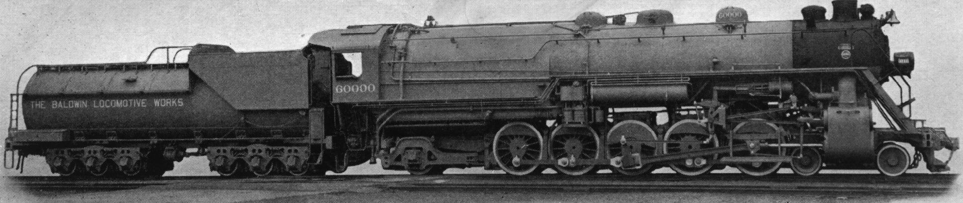
7. As a means of obtaining the higher expansion necessary to give economy with steam of 350 pounds per square inch, Locomotive 60,000 was designed with three cylinders compounded, the high-pressure steam being first admitted to the middle cylinder. After expansion there, the steam passes through the receiver in the cylinder saddle to the two outside cylinders where further expansion takes place.
Class 16-3-48/48-1/4-F - Locomotive Number 60000 Gauge, 4' 8 1/2"
High-pressure (1), inside            27" x 32"
Low-pressure (2), outside            27" x 32"
Valves                        Piston, 14" dia.
Type                                Wagon top
Diameter                                  84"
Working pressure                      350 lb.
Fuel                                Soft coal
Firebox

Type                               Water-tube
Length, total                         199.5"
Width,    "                             96"
Length of grate                     138.25"
Width  "    "                           86"
Water-tubes, number                    100
  "     "  , diameter                    4"

Boiler Tubes

Diameter                  5.5"   |  2.25"
Number                     50    |   206
Length                  23'0"    |  23'0"

Heating Surface*

Firebox                       745 sq. ft.
5.5" flues                   1645 sq. ft.
2.25" tubes                  2775 sq. ft.
Firebrick tubes                27 sq. ft.
Total                        5192 sq. ft.
Superheater                  1357 sq. ft.
Grate area                   82.5 sq. ft.
Diameter, outside                  63.5"
          center                     56"
journals, main                 12" x 13"
          others               11" x 13"
Diameter, front                     33"
Journals                       7" x 12"
Diameter, back                    45.5"
Journals                       9" x 14"
Driving                         22' 10"
Rigid                           16'  9"
Total engine                    45'  2"
Total engine and tender      86' 11.25"
in    working    order
On driving wheels           338,400 lb.
 " truck, front              57,500 lb.
 "  "   back                 61,600 lb.
Total engine                457,500 lb.
  "      "    and tender    700,900 lb.
Wheels, number                  Twelve
        diameter                   33"
Journals                      6" x 11"
Tank capacity        12,000 U. S. gal.
Fuel                          16 tons
        ---------------------------
Tractive force 82,500 lb*The figures here given are based on the outside diameters of the boiler tubes and flues, and the inside diameter of the superheater tubes. The figures given on page 50, which were used in computing the results of the tests, are based on the inside diameters of the boiler tubes and flues, and the outside diameter of the superheater tubes.
8. Steam pressures of 200 to 215 pounds per square inch have been currently used for a number of years, and in the last two or three years a considerable number of locomotives have been built for working steam pres- sures of 240 and 250 pounds per square inch. This latter is probably about the maximum pressure which can be carried successfully in boilers of the conventional design with fireboxes having flat sides braced by staybolts. The stayed firebox is the weakest point in a locomotive as ordinarily designed, and with pressures carried above 250 pounds per square inch a change in design is necessary to eliminate excessive trouble with staybolt breakage. The decision to use a pressure of 350 pounds per square inch in Locomotive 60,000 led to the adoption of a water tube firebox, and the elimination of all staybolts.
10. Apart from the modifications necessary to the use of the water-tube firebox and the high pressure, the boiler does not differ in principle from that of the con-ventional locomotive. The boiler barrel is of the usual firetube type having 206 2.25-inch tubes and a type A superheater carried in 50 5.5-inch flues.
11. The barrel consists of three courses, having plates respectively 1 5\16, 1 3\8 and 1.5 inches thick. The third course is sloped on top, increasing the shell diameter from 84 inches at the front end to 94 inches at the back. All circumferential seams are double riveted, and the longitudinal seams are of the so-called "saw-tooth" octuple riveted design, which provides a short caulking distance between the rivets. At the rear,the barrel is closed by a tube sheet, which is riveted to the shell in the same manner as the front tube sheet. The boiler tubes and flues are welded into the rear tube sheet. None of the studs tapped into the boiler passes all the way through the sheets, hence there can be no leaky studs or stays.
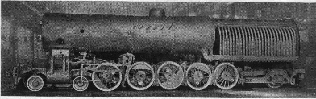
Locomotive Partially Erected:
Showing Completed Boiler One of the two
elbow pipes which deliver water from the boiler barrel to the mud-ring, is
plainly shown.
12. The firebox is of the water-tube type, each side wall consisting of 48 tubes 4 inches in diameter connecting a hollow cast steel mud-ring at the bottom to one of the horizontal cylindrical drums at the top. Outside of these side tubes a firebrick shell is built, over which are applied removable cover plates which are covered with magnesia sectional lagging and jacketed. The front and back walls of the firebox are of firebrick, and the opening between the two drums forming the crown of the firebox is also closed with firebrick.
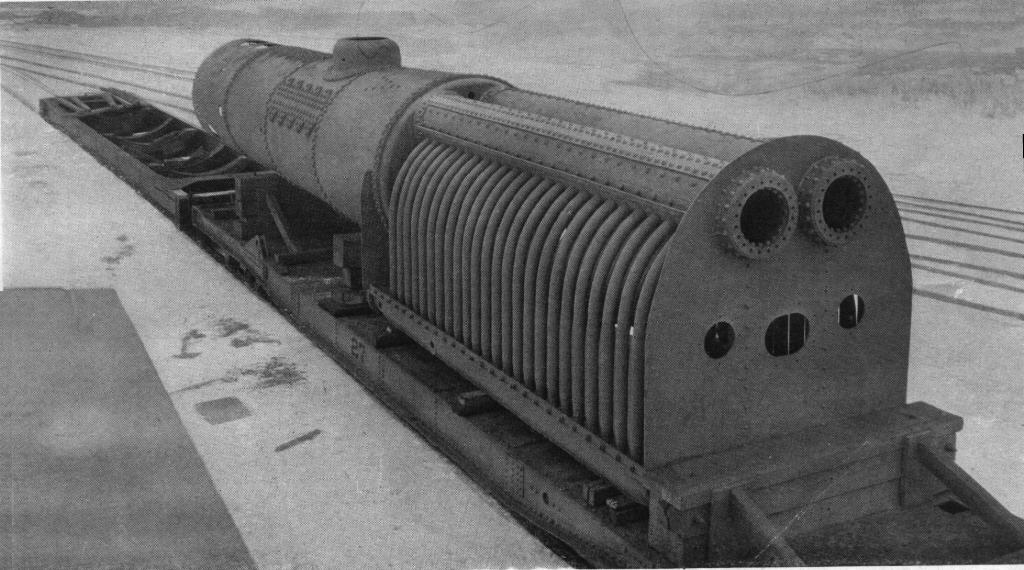
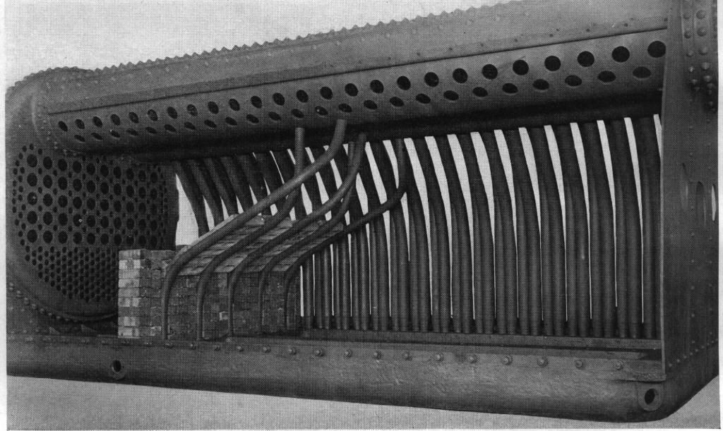
Boiler:
This view shows the openings in the rear firebox wall for
the fire-door and stoker, also the relative positions of the upper drums,
water tubes and mud-ring. No stay bolts are used in the construction of the
firebox.
This construction provides a boiler entirely free from staybolts and from flat surfaces requiring staybolts. This feature of the design gives it an important advantage when high steam pressures are to be carried. The depth of the firebox from the top of the mud-ring to the center line of the drums is 6 feet 6 inches. The total volume, including combustion chamber, reaches the large figure of 683 cubic feet. This gives 8.3 cubic feet of volume for each of the 82.5 square feet of grate area, which is a high relative volume for a modern locomotive, and aids in securing effective and efficient combustion.
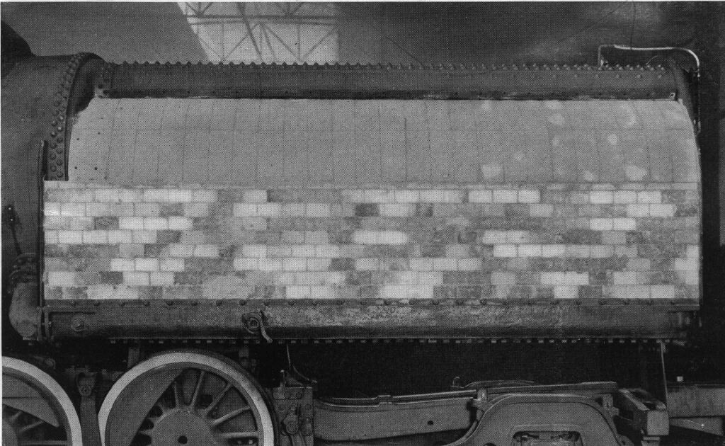
Firebox with Firebrick Applied.
13. The two drums are each 26 inches in diameter, and the transverse distance between their centers is 31 inches. They have a total length of 23 feet 6 inches, and extend into the boiler barrel a distance of 5 feet 6 inches ahead of the back tube sheet. The openings in this sheet, through which the drums pass, have flanges 6 5\8 inches in depth, to which the drums are double riveted Each drum is closed, at the rear, by a cover plate which is secured to an internal ring by means of studs, and is fitted with a copper gasket to keep the joint tight. By removing these covers the drums can be entered for purposes of inspection, and the water tubes can be "turbined" during washing- out, to remove any scale.
Cast Steel Mud-ring:
This view shows the under side of the mud-ring, the front being toward the
left. The holes for the elbow pipes to connect to the boiler barrel, and for
the plugs under the tubes, through which the tubes are rolled, are plainly
shown; also the lugs for the supporting plates. The transverse member carries
the firebrick arch and divides the grate from the combustion chamber.
Firebox Partially Assembled:
This view shows the firebox wall and arch, with the supporting tubes. The
water tubes on the left side of the firebox are not yet in place. The grate
is back of the arch, while the space ahead serves as a combustion chamber.
This can be done without removing any of the lower plugs, one of which is
placed in the mud-ring opposite each tube end for rolling the tubes.
Evidence obtained in road tests with different kinds of water shows very
light accumulation of scale in the drums and water-tubes. This indicates that
less frequent turbining and cleaning are necessary than with the con-ventional
type of stayed firebox.
The third course in the boiler barrel is sloped on top, and the two upper
drums are so located that their forward extensions come in contact with this
course and are riveted to it. This acts as a support for the drums, and tends
to counteract the cantilever effect of the long overhanging firebox.
Furthermore, to balance the effect of the pressure on the covers at the back
ends of the drums, three longitudinal stay rods are run from the forward end
of each drum to the front tube sheet. These rods are anchored to internal
braces which are riveted to the drum. This construction, together with a
system of braces connecting the front end of the mud-ring and the boiler
barrel, relieves the back tube sheet of any tendency to distortion, due to the
firebox overhang and the pressure on the drum heads.
14. The hollow cast steel mud-ring is connected to each upper drum by 48 tubes each 4 inches in diameter; and there are also four tubes connecting the drums to the back section of the mud-ring. All these tubes are swedged to a diameter of 3 inches at the mud-ring end, where they are rolled and belled, while at the drum end they are rolled, belled and welded. The tube holes in the mud-ring have two depressions rolled into them, into which the tubes lock themselves firmly when being rolled in. Water connection between the bottom of the boiler barrel and the front end of the mud-ring is made by two elbow pipes, each 9 inches in diameter, and placed right and left.
15. The mud-ring, which has a total length of 18 feet 2 inches and a width of 8 feet 5 inches, is cored throughout to permit water circulation. The rectangular outer frame is crossed by a central longitudinal member and also by a transverse member located about six feet back of the front end of the firebox. From this transverse member, which lies at the front end of the grate, five water tubes extend to the upper drums, and serve as supports for the brick arch. That portion of the firebox which is forward of the arch constitutes a combustion chamber and is closed, at the bottom, by a horizontal steel plate, and floored with firebrick. A Y-shaped cinder pocket is applied for cleaning this combustion chamber.
16. The locomotive is at present arranged for burning stoke, coal, and is equipped with a Duplex stoker. It has, how-ever, also been operated as an oil burner.
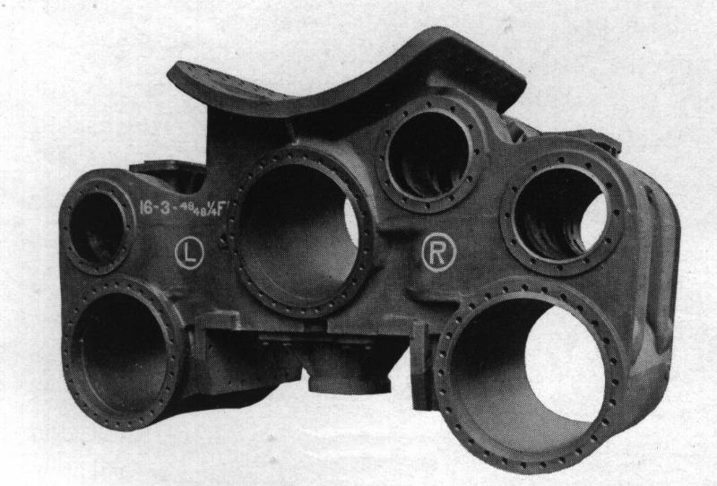
Cylinders:
This is a rear view of the one-piece cylinder casting completely finished and
drilled, with the truck center-pin in place.
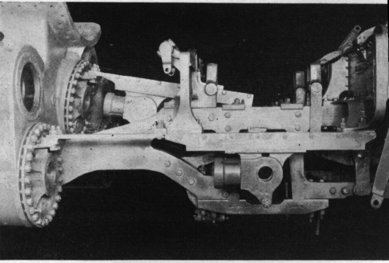
Guides and Crossheads:
This view shows the light design of crosshead used, also the method of
supporting the outside guides on bearers at each end.
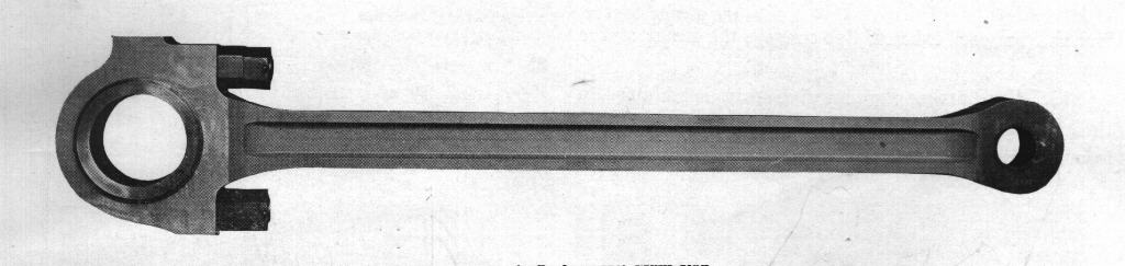
Inside (High-pressure) Main Rod::
The back end of this rod is of the marine type, with a floating bushing. The
brass is held in place by a U-shaped strap, which is forged in one piece with
the bolts.
17. The dome is placed on the second barrel course, and is connected with the superheater header by an in-ternal dry-pipe. A smokebox throttle of the multiple type is applied, and there is a shut-off valve for the steam supply in the dome.
18. The three cylinders, with their steam passages and steam chests, are formed in a single grey iron casting. The high-pressure steam chest is placed in the saddle, on the right-hand side, and is connected with the super-heater by a single steam pipe. All the piston valves are 14 inches in diameter, that for the high-pressure cylinder being arranged for inside admission, while the valves for the low-pressure (outside) cylinders are arranged for outside admission. The high-pressure exhaust is conveyed to the low-pressure steam chests through passages cored in the cylinder casting; while the exhaust from the low-pressure cylinders passes to the smokebox through outside pipes which terminate in a single exhaust nozzle. A Worthington feed-water heater is applied to this locomotive, and a branch from each exhaust pipe conveys the steam to the heater.
19. For starting purposes, live steam is admitted to the low-pressure cylinders through a 1.5-inch pipe leading from a manually-controlled valve in the cab. This creates a back pressure on the high-pressure piston,- relieving the same from the full effect of 350 pounds' pressure.
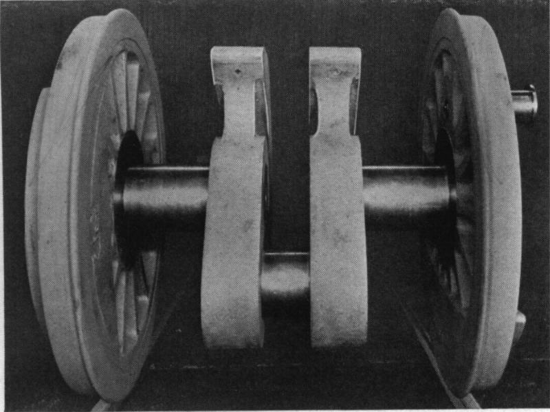
Crank Axle and Wheels Assembled:
This is the second pair of driving wheels, the outside cylinders being
connected to the third pair. The axle is built up of five pieces.
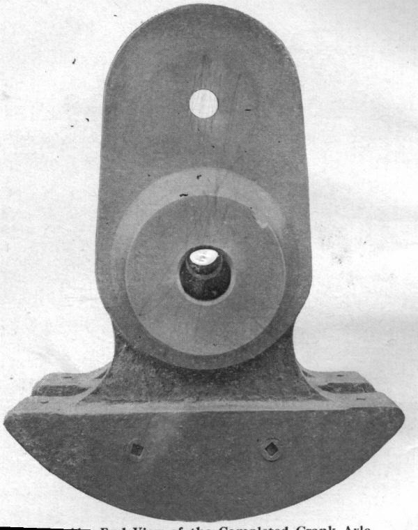
End View of the Completed Crank Axle:
The crank cheeks are of cast steel, each made in one piece with a counter-
balance weight which is cored hollow and filled with lead.
20. The two outside cranks are placed 90 degrees apart, so that there are four even exhausts per revolution, and the inside crank is placed at 135 degrees from each outside crank. The high-pressure piston is connected to the second pair of driving wheels, and the two low-pressure pistons to the third pair. All three piston heads are of the built-up type, with spiders of open hearth cast steel. The main and side rods are of carbon vanadium steel, while the driving axles, main crank pins and piston rods are of open hearth steel, heat treated, oil quenched and hollow bored. The cross-heads are of the underhung multiple bearing type, as developed by Mr. J. T. Wallis, now Assistant Vice President in Charge of Operation of the Pennsylvania Railroad, and adopted as standard for heavy power by that road. They work in guides having two inwardly projecting horizontal ribs on each side.
Cast Steel Valve Motion Bar:
The three links, the reverse shaft, the outside guides, the brake
cylinders, and a waist sheet, are supported by this casting.
21. Walschaerts valve gear is used, with an inde-pendent motion for each cylinder, but all controlled by one type B Ragonnet power reverse gear. The valve for the left-hand cylinder is operated from the left-hand main pin and crosshead in the usual way. The right-hand valve receives its lead from the right-hand cross-head, but the link for this cylinder is operated through a transverse shaft, by means of a connection to the left-hand crosshead. The return crank on the right-hand main pin is set to operate the valve for the inside cylinder, and this valve is given lead through a connection with the inside crosshead. The arrangement of the links, arms and rockers through which these connections are made, is shown in the accompanying drawings. The valve motion bearer is a single steel casting supporting practically the entire valve gear.
Side Elevation of Valve Motion
22. This locomotive, designed to traverse curves curving of 17 degrees, has flanged tires on all the wheels. Lateral motion boxes are applied to the first driving axle. The front truck has a swing bolster suspended on heart-shaped links, while the rear truck is of the Delta type, and is so designed that a booster can subsequently be applied if necessary. There is a continuous equalization system on each side of the locomotive, from the leading drivers to the rear truck.
23. The accessories are all operated by superheated steam at a pressure of 350 pounds, except the feed-water heater and injector, which use saturated steam at the same pressure.
24. The tender is carried on two six-wheeled trucks, and is of the Vanderbilt type with capacity for 12,000 gallons of water and 16 tons of coal.
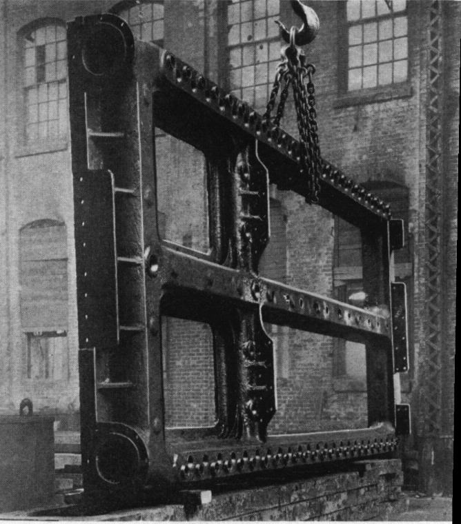
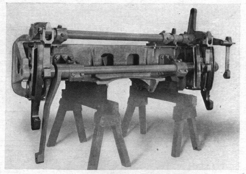
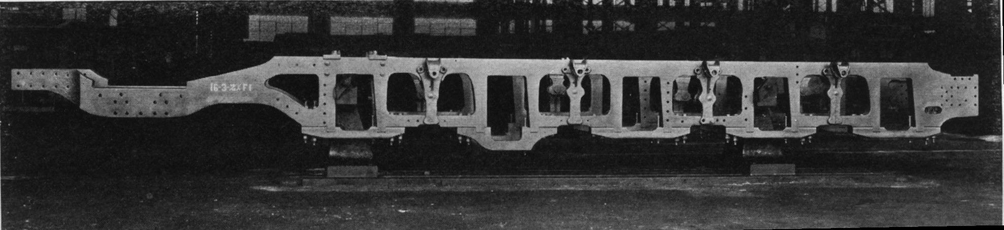
Frames Mounted on Erecting Forms In Erecting Shop:
The binders under the second pair of pedestals are bowed down so that
the cellars can be dropped for repacking without removing the binders.